Define the part and split
Identify the cast object, its largest cross-section, and the direction in which the mold should open. Mark where a parting line can follow the shape without trapping the finished piece.
Beginner workshop
This 3d mold maker tutorial for beginners shows how to move from a simple reference shape to a clean, testable mold design. Work in a deliberate order: define the parting logic, shape the cavity, inspect the result, and only then prepare an output for fabrication.
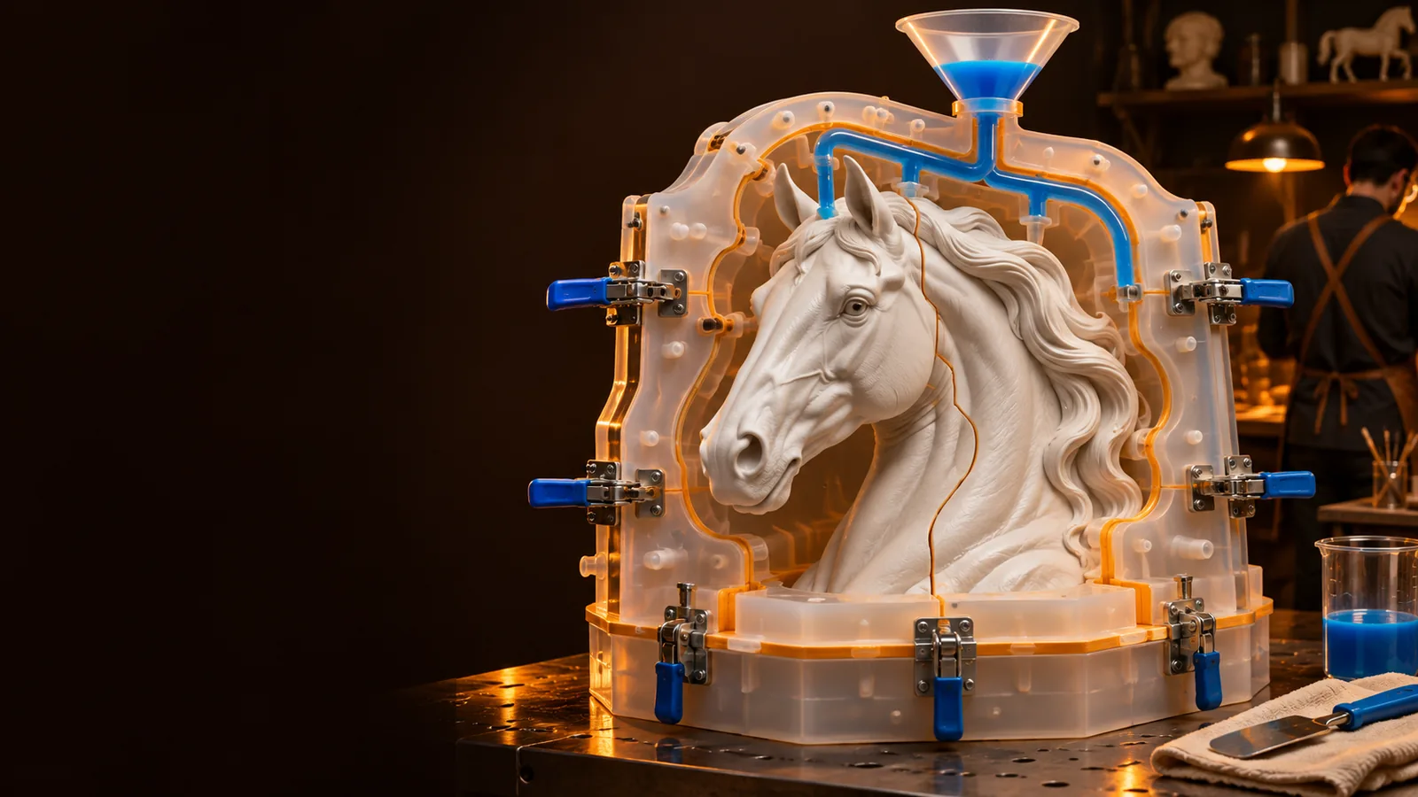
Gather the reference, dimensions, and fabrication constraints before opening the workspace. These checks prevent most avoidable redesigns later.
Use these three stages as a repeatable path from reference object to fabrication-ready mold concept.
Identify the cast object, its largest cross-section, and the direction in which the mold should open. Mark where a parting line can follow the shape without trapping the finished piece.
Create the negative space around the reference, then add a base, alignment features, vents, or a pour channel where the material and release method require them.
Rotate the mold, check wall thickness and clearances, preview both halves together, and make a small test before committing to the final output.
Most beginner problems are not mysterious software failures. They come from unclear opening direction, missing clearance, or skipping a visual inspection.
Move the split toward the widest section or divide the mold into additional parts.
Rotate the opening direction and inspect whether the finished cast can leave without force.
Increase the surrounding material and soften fragile corners where practical.
Add simple keys or pins and verify that the halves can only seat in the intended orientation.
Orbit around the complete assembly and inspect the cavity, vents, base, and exterior from several views.
Use a small, low-risk test to reveal seams, trapped areas, and fit problems before scaling up.
Once the basic workflow feels predictable, improve repeatability with clearer naming, smaller test loops, and geometry choices that support the material and process.
Compare the broader design workflow when you need more control over cavity geometry and inspection.
See how a generator-oriented workflow can turn a prepared mold concept into a printable direction.
Review silicone-focused considerations when flexibility, release, and surface detail shape the design.
These refinements make a beginner workflow easier to repeat and easier to diagnose when the result is not yet right.
Choose the opening direction before spending time on decorative detail. A visually attractive cavity can still fail if a wall, hook, or recessed feature locks the cast inside. Sketch the intended separation in your mind, then confirm it by viewing each half independently.
Model the mold as a working object rather than a perfect shell. Account for walls, a stable base, alignment features, a pour path, and enough access to clean or inspect the cavity. The right amount of clearance depends on the material and the fabrication method, so treat the first output as a test rather than a guarantee.
A short test cycle is often more valuable than adding complexity immediately. Start with a simple version, identify the first visible defect, change one variable, and compare the next result. Keep notes on what changed so successful settings and geometry choices can be reused.
The workflow has evolved from manual mold planning toward faster digital inspection, but the core decisions remain the same.
Makers studied the object, marked a separation path, and shaped blocks or flexible materials around the form. Release direction and access were practical decisions made before any digital preview existed.
Digital modeling made it easier to revise wall thickness, alignment features, vents, and cavity dimensions without rebuilding the entire form from scratch.
More makers could create physical prototypes quickly, making inspection and iteration central to the workflow rather than a final production step.
A mold maker can now begin with a written description or reference idea, then spend more attention on checking split logic, clearances, and fabrication constraints.
Describe the object, its approximate size, the material you plan to cast, and how the mold should open. Use the resulting concept as a starting point, then apply the checks in this guide before making a physical output.
These answers cover the questions beginners usually ask before making their first mold concept.
Start with a small object that has a clear outer shape and limited undercuts, such as a simple tile, rounded token, or shallow ornament. A straightforward first project lets you focus on parting, wall thickness, alignment, and inspection instead of solving several difficult geometry problems at once.
Describe the object, approximate dimensions, material being cast, desired number of mold parts, and the direction in which the mold should open. Also mention any required pour opening, vents, alignment features, or surface details so the concept reflects the intended process.
Check every deep recess, hook, overhang, and enclosed feature against the opening direction. View each mold half separately, then imagine the finished cast moving away from the cavity without bending or forcing it; if that path is unclear, revise the split or add a separate part.
A test is strongly recommended when the object, material, or process is unfamiliar. A small test can reveal trapped geometry, weak walls, poor alignment, surface defects, and an awkward pour path before those problems consume more material or time.
Not automatically. A generated or modeled concept still needs dimensional review, geometry inspection, material-specific decisions, and a fabrication check. Treat the first result as a design candidate, then verify it against the equipment and casting process you will actually use.