1
Best starting point
Online concept workflow
A written concept or rough shape
Desktop CAD workflow
A dimensioned part model
Mold planning
A 3d mold maker helps you turn a part idea into a mold plan. Describe the object, then check how the cavity, parting line, and release path would work before you fabricate anything.
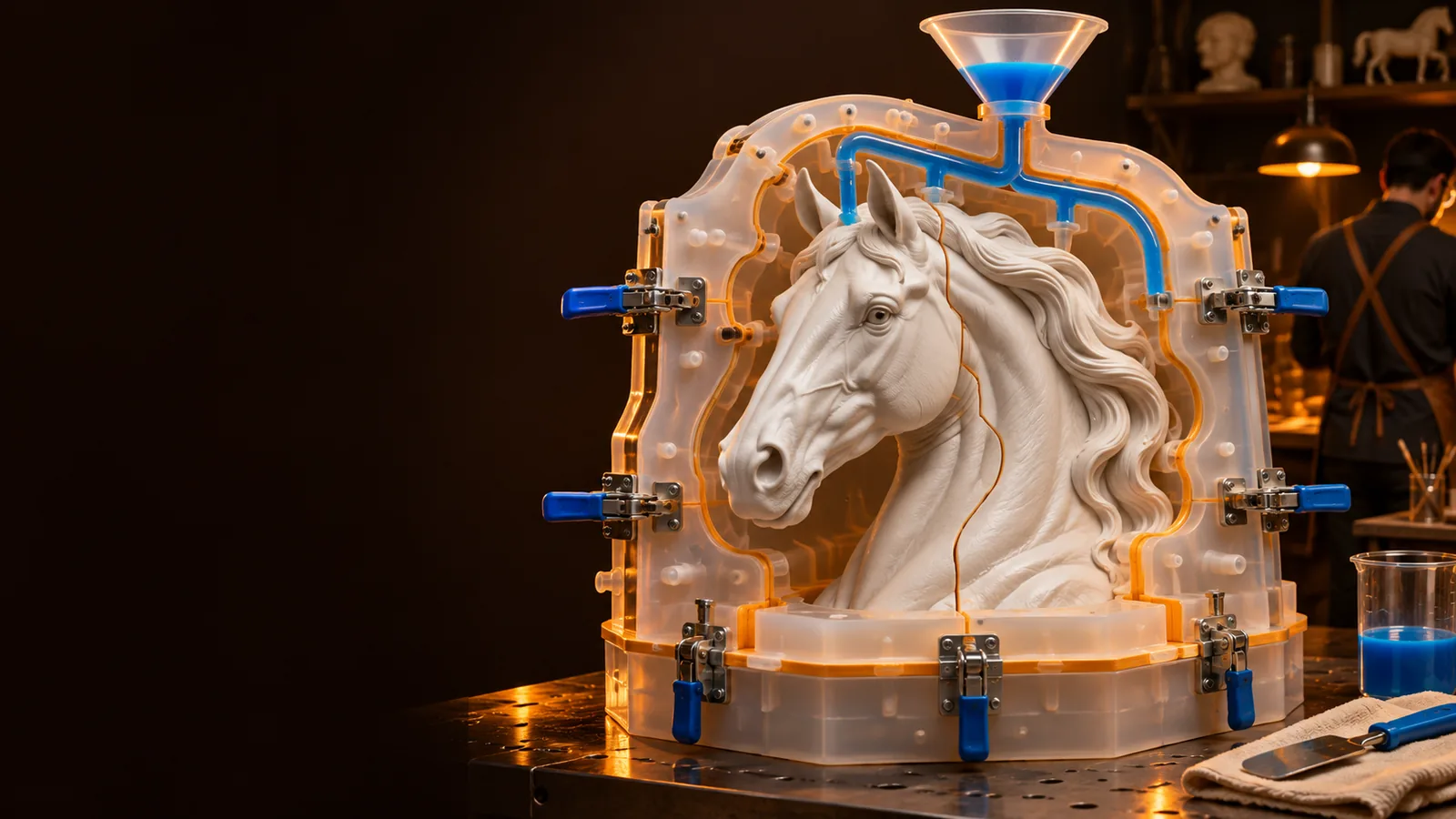
Use this comparison to decide whether early digital planning is enough or whether your project needs a more controlled CAD workflow.
Online concept workflow
A written concept or rough shape
Desktop CAD workflow
A dimensioned part model
Online concept workflow
Explore cavity and split ideas
Desktop CAD workflow
Control exact mold geometry
Online concept workflow
Requires independent verification
Desktop CAD workflow
Can be specified and measured
Online concept workflow
Compare possible placements
Desktop CAD workflow
Construct it against the model
Online concept workflow
Identify likely release problems
Desktop CAD workflow
Inspect and resolve them in detail
Online concept workflow
Review the concept against casting needs
Desktop CAD workflow
Validate dimensions and prepare manufacturing files
Different casting jobs put different demands on a 3d mold maker. Begin with the geometry you must preserve, then choose the checks that matter most.
You have a simple shape but are unsure where its two mold halves should separate.
Sketch a split and check whether the cast can leave the cavity. For a guided first project, see 3d mold maker tutorial for beginners.
3d mold maker tutorial for beginnersYou need a master, a containment box, and a pour route that stays accessible.
Plan the box around the master without assuming every overhang will release cleanly. Review 3d printed molds for silicone for material-specific considerations.
3d printed molds for siliconeYour small part has fine details where trapped air could spoil the result.
Consider fill and vent positions alongside the parting line. The 3d printed molds for resin guide covers the casting context.
3d printed molds for resinYour part needs repeatable alignment and dimensions that must survive prototyping.
Use the concept to identify questions, then verify the geometry in a measured workflow. Compare approaches in 3d mold design software.
3d mold design softwareAn online starting point is most useful when each pass answers a specific fabrication question rather than merely producing a convincing picture.
State the object's approximate size, intended casting material, visible surfaces, and where a fill opening could go. Mention features that must remain sharp or dimensionally accurate.
Look for a sensible parting line, enough material around the cavity, and a removal direction for the cast. Reconsider deep undercuts or enclosed shapes before refining details.
Check wall thickness, alignment, fill and vent access, and print orientation in an appropriate modeling workflow. Treat a visual concept as a plan to verify, not a tested manufacturing file.
A 3d mold maker can help frame a design problem, but a plausible cavity is not proof that a mold will print, seal, fill, or release successfully.
Without scale, wall and clearance decisions cannot be judged.
Check every overhang against the planned release direction.
Material behavior affects release, sealing, and surface preparation.
Measure these in a suitable design workflow before fabrication.
Add them where the chosen casting process calls for them.
Visual references make it easier to ask useful questions about a design. They do not replace a measured model or a physical test cast.
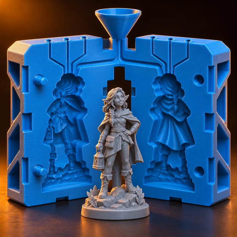 Shape
01
Keep the original object's important surfaces in view while planning the negative space around it. A 3d mold maker concept should make it easier to spot fragile details, narrow cavities, and areas where a casting material may struggle to flow.
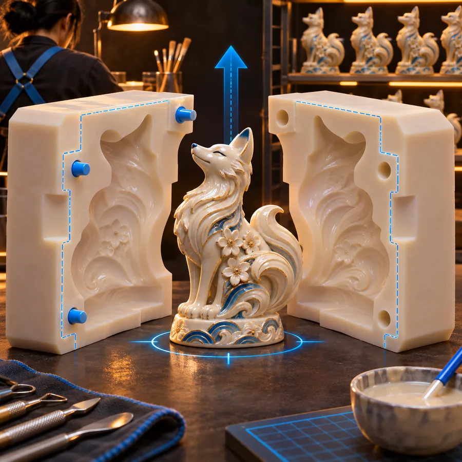 Release
02
Imagine opening the mold and removing the finished part without tearing a flexible mold or trapping a rigid one. If the shape cannot move out along the proposed path, change the split, reconsider the geometry, or plan additional pieces.
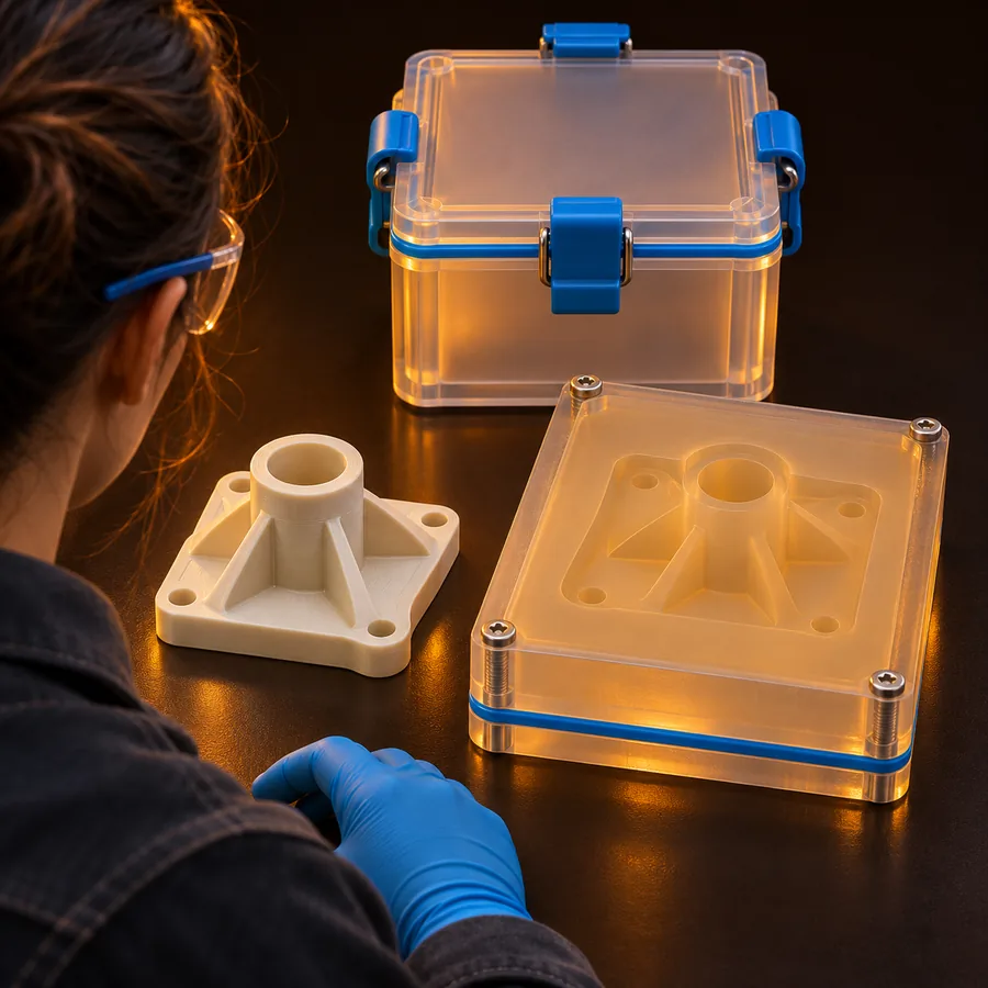 Validation
03
Before treating a design as print-ready, inspect how it will be oriented, filled, vented, joined, and cleaned. An online concept is a useful starting point; fabrication decisions still need dimensional checks and, often, a small test.
Bring a specific part, approximate dimensions, and casting material. Use the resulting concept to ask better questions about the cavity and split, then verify the geometry before you print or cast.
Yes, an online workflow can help you explore the cavity, parting line, and overall layout before fabrication. Check whether the particular tool accepts the kind of input you have, and verify any proposed geometry before relying on it for a print.
Not always for early concept planning: a description, sketch, or measured reference can help define the problem. For an accurate cavity that fits a specific part, you will eventually need reliable geometry and dimensions.
Do not assume that a visual result is a printable mold. Check that the final geometry is complete and scaled correctly, with suitable walls, clearances, openings, and release paths, using tools appropriate to the intended fabrication process.
Look for a split that lets the cast leave each half without catching on undercuts. Also consider which surfaces will show a seam and whether the mold halves can be aligned and held together.
The part shape may be the same, but the mold construction and casting setup can differ. Review material compatibility, release, fill and vent locations, and surface preparation for the specific process you intend to use.